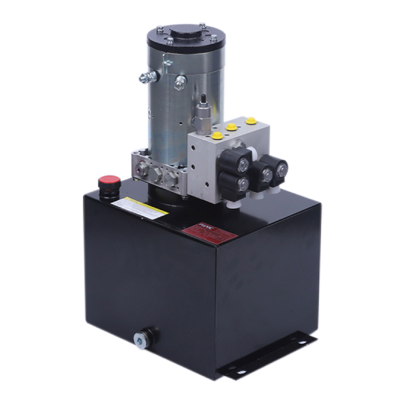
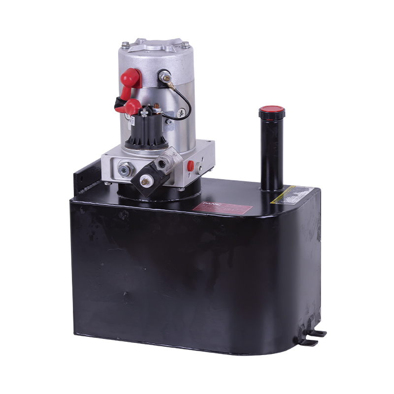
Что на самом деле означает определение размера привода клапана
Правильный ответ на вопрос: «Насколько большим должен быть мой привод клапана?» Все просто: привод должен создавать больший крутящий момент, чем требует клапан, в худшей точке хода и при минимально возможном условии подачи. Каждый хороший метод определения размера — это просто структурированный способ доказать это одно условие. Стандартной промышленной отправной точкой является минимальный запас прочности по крутящему моменту 25 % выше опубликованного изготовителем клапана максимального крутящего момента.
Привод слишком маленького размера заглохнет до того, как клапан достигнет своего конечного упора, оставит клапан лишь частично открытым или закрытым, потребляет чрезмерный ток и в конечном итоге выйдет из строя из-за перегрева или постоянной остановки. Привод слишком большого размера может нанести такой же вред: он врезает клапан в седла, сгибает штоки, создает чрезмерную нагрузку на трим и затрудняет точное управление. Таким образом, определение размера заключается не в выборе самого большого привода, который вы можете найти. Речь идет о доказательстве того, что нижняя точка кривой привода находится над верхней точкой кривой крутящего момента клапана.
Итог: Недостаточный размер приводит к выходу из строя, а неосторожный превышение размера приводит к механическим повреждениям. Документированный расчет крутящего момента защищает как клапан, так и привод, а также дает команде проекта запись, которую они могут перепроверить при изменении условий процесса.
Значения крутящего момента, которые определяют каждый расчет размеров
Выбор размера начинается с данных о крутящем моменте, предоставленных производителем клапана. Для четвертьоборотного клапана вам нужны четыре значения: момент разрушения, рабочий момент, конечный момент и максимальный момент отключения при расчетном перепаде давления. Для линейного клапана вам нужны эквивалентные значения тяги. Без этого технического паспорта любой выбор привода остается лишь догадкой.
Четвертьоборотные клапаны: тормозной, рабочий и конечный крутящий момент
- Разрывной крутящий момент — крутящий момент, необходимый для начала вращения и смещения шара, дроссельной заслонки или плунжера. Обычно это самое высокое значение в цикле, особенно для клапанов с упругим седлом, в которых седло захватывает запорный элемент.
- Рабочий крутящий момент — крутящий момент, необходимый для поддержания движения клапана. Оно состоит в основном из трения уплотнения, трения подшипника и крутящего момента потока, действующего на диск или шар.
- Конечный крутящий момент появляется в полностью открытом или полностью закрытом положении из-за сжатия седла, остановки хода, а в некоторых конструкциях из-за нагрузки технологического давления на запирающий элемент.
Линейные клапаны: нагрузка на седло, трение уплотнения и дисбаланс
- Нагрузка на сиденье — это сила, необходимая для вдавливания плунжера или затвора в седло для достижения требуемого класса запирания. Для клапанов с металлическим седлом оно часто выше, чем для клапанов с мягким седлом.
- Трение упаковки сопротивление штока, скользящего через сальниковую коробку. Оно увеличивается по мере старения уплотнения и всегда выше после того, как клапан проработал несколько циклов.
- Гидравлический дисбаланс — это сила технологического давления, действующая на эффективную площадь пробки. Для односедельного клапана, работающего при высоком перепаде давления, этот термин может иметь решающее значение при расчете тяги.
Компоненты крутящего момента для четвертьоборотных клапанов и конструктивные данные следует запросить у производителя клапана. | Компонент крутящего момента | Когда это важно | Что движет этим |
| Разрывной крутящий момент | Начало инсульта | Натяг седла, перепад давления, закаленный или состаренный материал седла. |
| Рабочий крутящий момент | Средний ход | Трение упаковки, bearing friction, flow-induced torque |
| Конечный крутящий момент | Конечные остановки | Сжатие седла, ограничители хода, нагрузка давлением в закрытом положении |
Пошаговая процедура определения размера привода клапана
Используйте эту процедуру как для новых клапанов, так и для проектов модернизации. Он работает для пневматических, гидравлических и электрических приводов, при этом между технологиями меняется только расчет подачи крутящего момента.
- Запросите таблицу моментов затяжки клапанов. Получите значения тормозного, рабочего и конечного крутящего момента при максимальном перепаде давления и максимальной температуре. Также обратите внимание на размеры привода штока и размер монтажного фланца.
- Примените коэффициент безопасности. Умножьте максимальный опубликованный крутящий момент клапана как минимум на 1,25. Для грязных, абразивных или многоцикловых работ используйте значение 1,5 или выше.
- Определите положение безопасности. Решите, должен ли клапан открываться, закрываться или оставаться в положении при потере питания или воздуха. Это определяет тип привода и требования к пружине.
- Уточните условия поставки. Запишите гарантированное минимальное пневматическое давление, диапазон гидравлического давления или напряжение электропитания, доступное в месте расположения привода.
- Выберите пробный привод. Сравните выходной крутящий момент, указанный в каталоге приводов, при минимальном давлении питания с требуемым крутящим моментом, включая коэффициент запаса прочности.
- Проверьте каждую точку крутящего момента. Для приводов с пружинным возвратом проверьте крутящие моменты пневмопуска, пневмоконца, пружинного пуска и конца пружины. Для приводов двойного действия проверьте выходную мощность при минимальном давлении подачи в обоих направлениях.
- Проверьте время хода и аксессуары. Убедитесь, что привод перемещает клапан в пределах времени процесса, что монтажный интерфейс соответствует размерам ISO 5211 и что позиционеры, концевые выключатели или пилотные соленоиды не перегружают выход привода.
Эта последовательность выглядит простой, но именно на этапе проверки сохраняется большинство ошибок определения размера. Всегда выполняйте проверку крутящего момента по четырем точкам, прежде чем утвердить привод с пружинным возвратом к покупке.
Факторы безопасности: насколько достаточен запас крутящего момента
Коэффициент безопасности – это самая простая и наиболее неправильно понимаемая часть расчета привода. Не разрешается выбирать случайную модель большего размера. Это преднамеренный допуск на неопределенности, которые возникают в каждой реальной установке: допуск измерения крутящего момента, старение уплотнения, износ седла, нерасчетный перепад давления и загрязнение технологической среды. Каждый из них увеличивает крутящий момент, фактически требуемый клапаном, по сравнению с техническими данными нового клапана.
Типичные коэффициенты запаса прочности привода в зависимости от условий эксплуатации. Это рекомендации по применению, а не юридические требования. | Условия эксплуатации | Типичная маржа | Причина маржи |
| Чистая вода, воздух, общие услуги | 1.25 | Чистая среда, низкий износ, стабильное трение набивки |
| Технологические жидкости с отложениями или твердыми частицами | 1.5 | Отложения на штоке и седле со временем увеличивают тормозной момент |
| Защитная изоляция, противопожарные и газовые обязанности | от 1,5 до 2,0 | Клапан должен закрываться даже при наличии корродированных деталей и поврежденной упаковки. |
| Большое количество циклов или быстрый ход | 1.5 | Износ постоянно увеличивает крутящий момент на протяжении тысяч циклов. |
Запишите выбранный коэффициент запаса прочности в техническую спецификацию, чтобы следующий инженер или поставщик комплекта клапанов мог точно воспроизвести ваши расчеты. Незадокументированная маржа будет пересматриваться на каждом совещании по проекту, и в результате часто для урегулирования спора покупают неоправданно большой привод.
Безопасный подбор параметров с пружинным возвратом: проверка по четырем пунктам
Привод с пружинным возвратом создает разный крутящий момент в каждом положении, поскольку пружина сжимается при ходе привода. Крутящий момент воздуха самый высокий, когда привод впервые начинает двигаться, и самый низкий, когда пружина полностью сжата. Момент пружины обратный: минимальный в открытом положении, максимальный в закрытом. Вот почему одного значения крутящего момента никогда не бывает достаточно для отказоустойчивого привода.
Для привода с пружинным возвратом, закрывающегося при отказе, проверьте эти четыре рабочие точки по порядку:
- Пневматический запуск (клапан закрыт, подается воздух): привод должен преодолеть момент разрушения клапана давлением воздуха и начать открываться. Крутящий момент запуска воздуха должен быть больше крутящего момента торможения.
- Воздушная часть (клапан открыт, пружина сжата): крутящий момент воздуха находится в самой низкой точке. Он все равно должен быть больше рабочего крутящего момента, иначе клапан замедлится и остановится, прежде чем достигнет открытого положения.
- Пружинный запуск (клапан открыт, воздух стравлен): пружина начинает закрывать клапан. Пусковой крутящий момент пружины должен быть выше рабочего крутящего момента, иначе клапан заглохнет в середине хода.
- Конец пружины (клапан закрыт, пружина установлена): момент пружины максимальный. Момент на конце пружины должен быть достаточно высоким, чтобы полностью посадить клапан против перепада давления.
Распространенной ошибкой является проверка только момента затяжки пружины. Во многих конструкциях с кулисным механизмом крутящий момент воздуха падает на 30–50 % между открытым и закрытым положениями. Если крутящий момент на воздушной головке падает ниже рабочего крутящего момента, клапан при нормальной работе будет приближаться к закрытому положению, и позиционер будет бороться с приводом весь день.
Рабочий пример: определение размера пневматического привода для поворотной заслонки
В следующем расчете используются иллюстративные значения. Прежде чем принимать решение о покупке, замените их данными о крутящем моменте от вашего конкретного производителя клапана.
Технологическому предприятию необходимо автоматизировать 6-дюймовый (DN150) дисковый затвор с упругим седлом для изоляции воды. Производитель клапана указывает момент срабатывания 200 Н·м , рабочий крутящий момент 110 Н·м , и конечный крутящий момент 90 Н·м при перепаде давления отключения 10 бар. Доступное пневматическое питание 5,5 бар . Клапан должен не закрываться при потере воздуха.
- Требуемая минимальная мощность = 200 Н·м × 1,25 = 250 Н·м .
- При аварийном закрытии требуется привод с пружинным возвратом, а крутящий момент на конце пружины должен составлять не менее 250 Н·м.
- Возможный привод с кулисным механизмом с пружинным возвратом обеспечивает: пневматический пусковой момент 380 Н·м, пневматический конец 300 Н·м, пружинный пуск 160 Н·м, пружинный конец 275 Н·м, все измерено при давлении питания 5,5 бар.
- Проверка по четырем пунктам обобщена в таблице ниже.
Четырехточечная проверка для дроссельной заслонки, закрывающейся при отказе, в рассматриваемом примере. Все значения крутящего момента в Н·м. | Точка проверки | Требуемый крутящий момент | Выход привода | Результат |
| Воздушный запуск (открытие) | 200 (перерыв) | 380 | Пройти |
| Воздушная часть (полностью открыта) | 110 (бег) | 300 | Пройти |
| Начало весны (закрытие) | 110 (бег) | 160 | Пройти |
| Весенний конец (закрыт) | 200 (посадочных мест) | 275 | Пройти |
Теперь проверьте тот же привод при пониженном давлении питания 4 бар. Пневматическая мощность линейно изменяется в зависимости от давления: начало подачи воздуха становится 380 × 4 ÷ 5,5 = 276 Н·м, а усилие подачи воздуха становится 218 Н·м. Значения пружин не меняются. Запас открытия сокращается со 180 Н·м до 76 Н·м, но конфигурация все равно проходит. Это правильный способ проверки давления: всегда проверяйте при минимальной подаче, которую вы можете гарантировать, а не при номинальном давлении установки.
Выбор гидравлического привода для работы с высоким крутящим моментом и в условиях ограниченного пространства
Электрическим и пневматическим приводам уделяется больше всего внимания в общих руководствах по определению размеров, но гидравлические приводы обеспечивают лучшую удельную мощность из трех технологий. Поскольку гидравлическая система обычно работает при давлении от 70 до 210 бар вместо 3–8 бар для технологического воздуха, компактный гидравлический цилиндр может создавать крутящий момент, который потребовал бы гораздо более мощного пневматического привода.
Этапы определения размеров гидравлических приводов
При определении размера гидравлического привода имеют значение два различия. Во-первых, максимальная производительность определяется настройкой предохранительного клапана, а не максимальным номинальным давлением насоса. Во-вторых, крутящий момент привода рассчитывается на основе эффективной площади поршня и перепада давления на поршне в момент работы. Действуйте в обратном порядке: сначала выберите настройку предохранительного клапана, поскольку она определяет потолок крутящего момента, затем определите путь потока для требуемого времени хода, а затем убедитесь, что насос и двигатель могут обеспечить поток.
Компоненты, дополняющие гидравлический контур
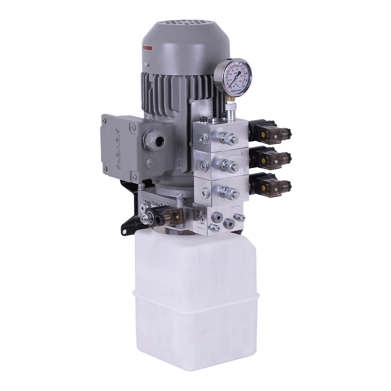
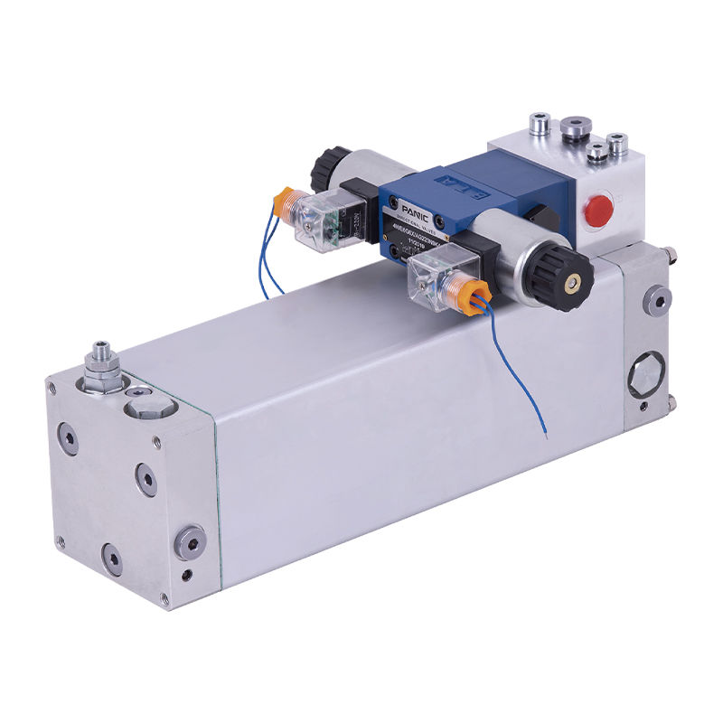
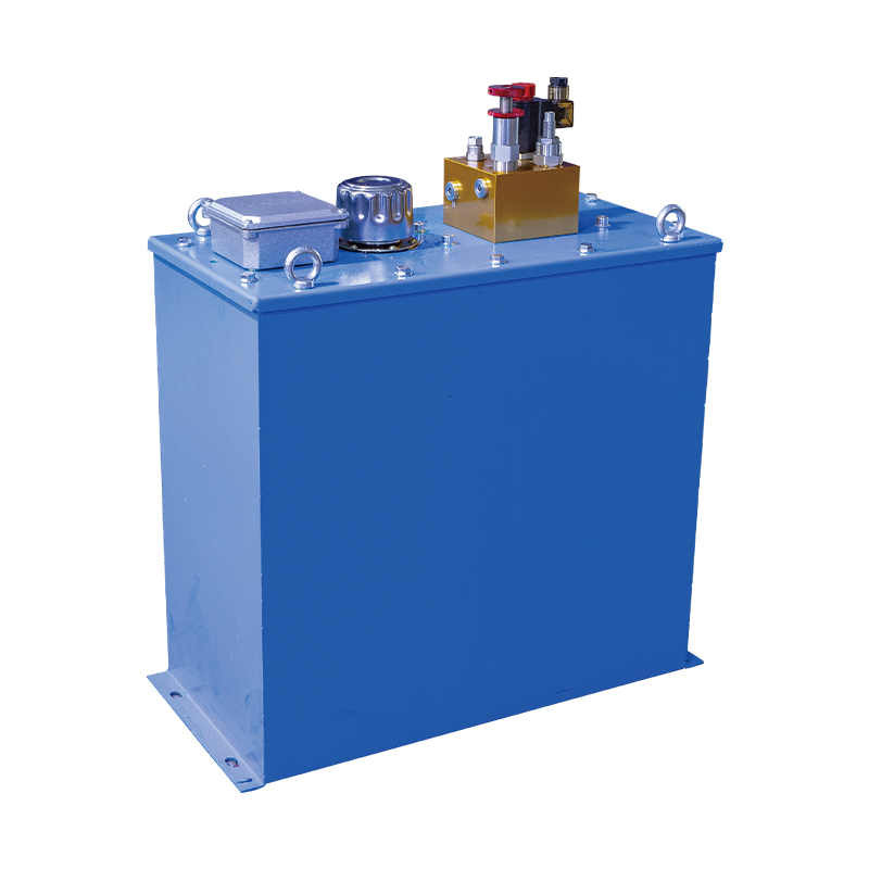
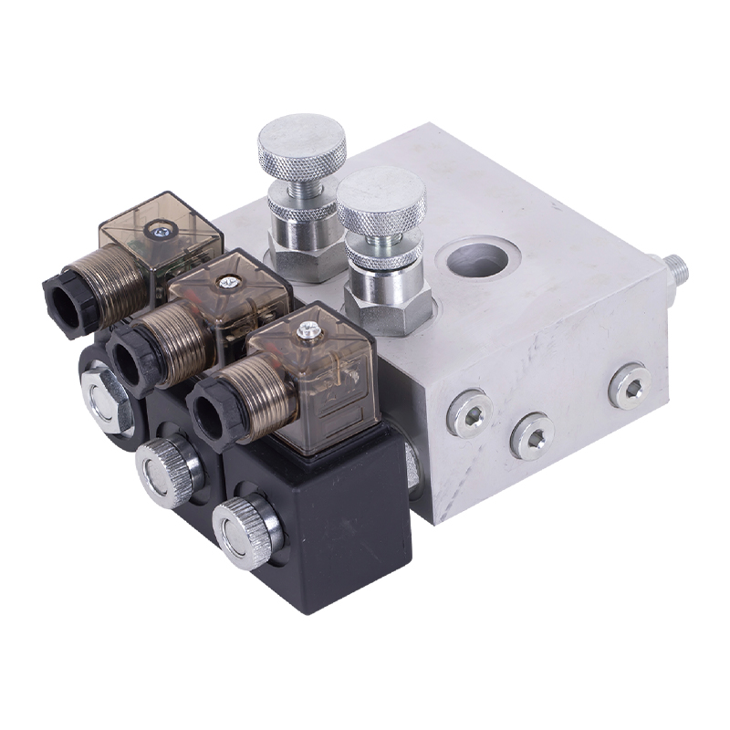
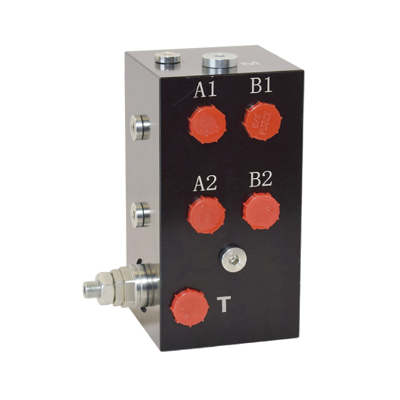
Контур управления — это то место, где возникает большинство проблем с гидравлическим определением размеров. В стандартной комплектации клапан-привод гидравлический электромагнитный клапан переключает направление потока для выдвижения и втягивания привода. А регулирующий клапан силового агрегата регулирует скорость потока так, чтобы время хода оставалось в пределах предела процесса. А предохранительный клапан силового агрегата защищает седло клапана от скачков крутящего момента, ограничивая максимальное давление в системе.
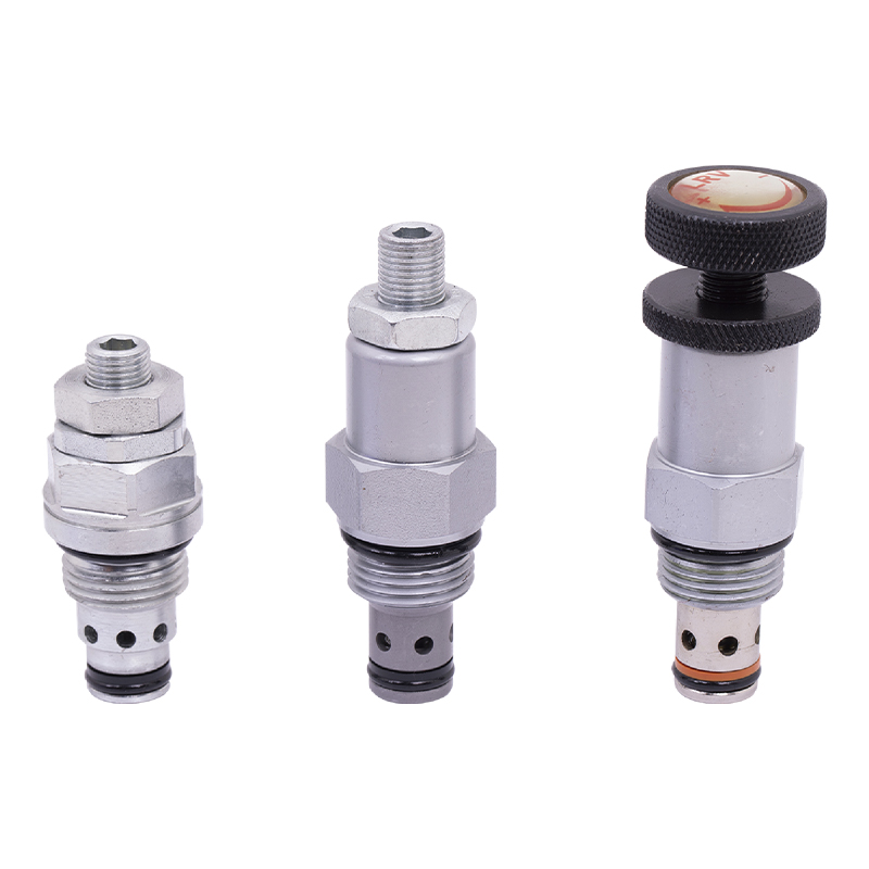 Производители предохранительных клапанов силового агрегата, оптовая фабрика - Ningbo Panic Hydrauli КО. технологии паники Нинбо гидравлическое, Лтд - китайские производители предохранительных клапанов силового агрегата и фабрика ОЭМ/ОДМ, мы специализируемся на оптовой продаже... Посмотреть продукт →
 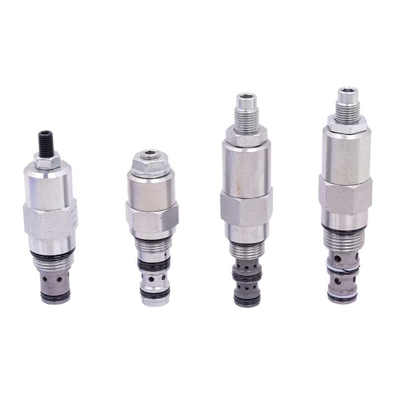 Производители регулирующих клапанов силового агрегата, оптовая фабрика - Ningbo Panic Hydr Ningbo Panic Hydraulic Technology Co., Ltd является китайским производителем регулирующих клапанов силового агрегата и заводом OEM/ODM. Мы специализируемся на оптовых продажах ... Посмотреть продукт →
 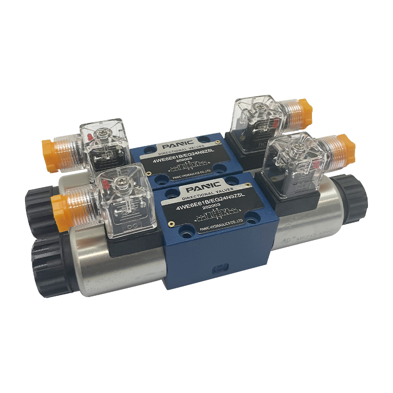 Производители электромагнитных клапанов, Завод сменных электромагнитных клапанов Ningbo Panic Hydraulic Technology Co., Ltd является китайским производителем электромагнитных клапанов OEM/ODM и заводом по производству вставных электромагнитных клапанов. Мы специализируемся ... Посмотреть продукт →
 Последовательность определения размера пакета гидравлического привода проста. Рассчитайте необходимый крутящий момент по паспорту клапана и коэффициенту запаса прочности. Преобразуйте крутящий момент в необходимый перепад давления, используя эффективную площадь привода и моментное плечо. Установите предохранительный клапан на значение, комфортно превышающее это давление, обычно на 10–20 % выше, чтобы привод мог развивать полный крутящий момент без подъема предохранительного клапана. Затем подберите насос и двигатель таким образом, чтобы расхода было достаточно для открытия клапана в течение необходимого времени. Наконец, убедитесь, что электромагнитный клапан имеет достаточно большой коэффициент расхода, и позвольте регулирующему клапану точно настроить скорость хода.
Все это предполагает, что вы понимаете принцип работы гидравлической системы особенно то, как взаимодействуют расход насоса, реакция клапана и смещение привода во время быстрого хода. На практике гидравлические силовые агрегаты относительно просты в эксплуатации по сравнению с механическими силовыми агрегатами. , поэтому срабатывание гидравлического клапана часто встречается на запорных клапанах большого диаметра, воротах резервуарных парков и тяжелом подъемном оборудовании.
Семь ошибок при выборе размеров, которые приводят к сбоям в работе
Большинство неисправностей привода не вызваны дефектом продукта. Они вызваны неполным расчетом на этапе проектирования. Эти семь ошибок появляются снова и снова в полевых отчетах и протоколах ввода в эксплуатацию.
- Выбор размера основан на рабочем моменте, а не на моменте торможения. Клапан обычно запускается из состояния покоя при полном перепаде давления, поэтому тормозной момент — это величина, которая останавливает привод недостаточного размера.
- Выбор размера при номинальном давлении питания. Подача воздуха и гидравлики на заводе колеблется. Если выходное давление привода рассчитано на 5,5 бар, а реальный минимум составляет 4 бар, запас безопасности может полностью исчезнуть.
- Добавляем коэффициент безопасности дважды. Если производитель арматуры уже включил запас в опубликованный тормозной момент, дополнительные 25% могут привести к увеличению выбора на один или два размера.
- Увеличение размера для безопасности. Привод слишком большого размера врезается в седло клапана, сгибает штоки и делает управление нестабильным. Маржа предназначена для покрытия неопределенности, а не для компенсации грубых операций.
- Проверка только пружинного конца привода с пружинным возвратом. Крутящий момент пневмоблока в конструкции с кулисным механизмом может упасть на 30–50 %, и эта нижняя точка может быть причиной того, что клапан никогда не достигает упора открытия.
- Игнорирование интерфейса монтажа. Правильный расчет крутящего момента бесполезен, если фланец привода не соответствует размерам привода штока клапана. Подтверждайте интерфейс перед заказом, а не во время ввода в эксплуатацию.
- Пропуск проверки времени хода. Привод с большим крутящим моментом все равно может быть слишком медленным для аварийной блокировки технологического процесса. Всегда проверяйте полное время перемещения с включенным пилотным клапаном и линией подачи.
Контрольный список размеров для предварительного заказа
Прежде чем завершить оформление заказа на покупку, просмотрите этот контрольный список, положив перед собой паспорт клапана и каталог приводов. Отрицательный ответ по любому пункту означает, что размер не завершен.
- Подтвердите разрыв клапана, работу и конечный крутящий момент при максимальном перепаде давления и максимальной рабочей температуре.
- Примените документированный коэффициент запаса прочности не менее 1,25 и укажите его в спецификации.
- Определите безопасное положение и проверьте крутящий момент на конце пружины и пусковом моменте пружины для устройств с пружинным возвратом.
- Запишите гарантированное минимальное давление питания, доступное на приводе, и размер, используя это значение.
- Проверьте размер монтажного фланца ISO 5211 и размеры привода штока.
- Проверьте время полного хода на соответствие технологическим требованиям, включая потери в соленоиде и линии.
- Укажите все аксессуары: позиционер, концевые выключатели, электромагнитный пилотный клапан, устройство ручного дублирования и местный индикатор положения.
- Прежде чем утвердить заказ, повторите проверку крутящего момента еще раз в условиях минимальной подачи.
Если вы собираете гидравлический силовой агрегат для привода привода, просмотрите наше руководство для покупателя гидравлической силовой установки переменного тока прежде чем выбрать размер насоса и двигателя. Требуемый крутящий момент от привода становится требованиями к давлению и расходу, которые должен обеспечить силовой агрегат.
Часто задаваемые вопросы: Часто задаваемые инженерами вопросы по выбору привода клапана
Каково правило 25% запаса прочности при выборе привода?
Правило 25% означает, что выходной крутящий момент привода должен быть как минимум в 1,25 раза больше максимального заявленного момента срабатывания клапана. Он охватывает неопределенность измерений, старение уплотнений и незначительные различия между испытанным клапаном и поставленным клапаном. Относитесь к нему как к полу, а не как к цели. Увеличьте его до 1,5 или выше, если процесс грязный, абразивный или критический для безопасности.
Почему приводы с пружинным возвратом нуждаются в четырехточечной проверке крутящего момента?
Потому что выходной крутящий момент меняется в зависимости от положения. Крутящий момент воздуха самый высокий в начале хода и самый низкий, когда пружина полностью сжата; Момент пружины обратный. Одно значение в каталоге не может сказать вам, будет ли клапан полностью открываться, полностью закрываться и удерживать положение на протяжении всего хода. Это можно сделать только при значениях начала подачи воздуха, конца подачи воздуха, начала пружины и конца пружины.
Вреден ли завышенный размер привода?
Да. Превышение примерно в 2 раза требуемого разрушающего момента может сжать седло за пределы расчетного диапазона, погнуть шток в конструкциях с боковой нагрузкой, вызвать гидравлический удар во время быстрого закрытия и очень затруднить настройку контура управления. Целью является доказанный положительный запас, а не самый большой привод в каталоге.
Как давление питания влияет на выходной крутящий момент привода?
Для пневматических приводов выходной крутящий момент изменяется почти линейно в зависимости от давления питания. Привод, развивающий крутящий момент 380 Н·м при 5,5 бар, развивает всего 276 Н·м при 4 бар. Для гидравлических приводов крутящий момент зависит от перепада давления на поршне, который ограничивается настройкой предохранительного клапана. Всегда выбирайте минимальное давление, которое может выдержать система.
Какие данные о крутящем моменте мне следует запросить у производителя клапана?
Запросите разрушающий момент, рабочий момент и конечный момент при максимальном перепаде давления и максимальной температуре для обоих направлений потока. Для линейных клапанов укажите нагрузку на седло, трение уплотнения и зону неуравновешенности. Также спросите, включают ли опубликованные значения запас прочности, чтобы не добавлять второй запас сверху.
Когда следует выбирать гидравлический привод вместо пневматического или электрического?
Выбирайте гидравлический привод, когда требуемый крутящий момент очень высок, когда пространство для установки ограничено, когда воздух в системе ненадежен или плохо осушен, или когда вам нужна постоянная сила, независимая от колебаний подачи воздуха. Гидравлические системы также хорошо подходят для запорных клапанов большого диаметра, подъемников и мобильного оборудования, где уже имеется источник гидравлической энергии.
Итоговый вывод по размерам
Выбор привода клапана — это цикл проверки, а не простой поиск в таблице. Повторно запускайте его всякий раз, когда изменяются размер клапана, класс давления, технологическая среда или давление питания. Документируйте все вводимые данные — значение момента разрыва, коэффициент запаса прочности, крутящий момент на конце пружины и минимальное давление питания, которое вы действительно гарантируете, — и храните этот файл вместе с паспортом клапана.
Привод, который проходит все четыре проверки крутящего момента при минимальной подаче, соответствует требуемому времени хода, подходит к стандартному монтажному фланцу и оставляет документированный запас, является правильным. Вот и вся работа — если правильно ее выполнить, она предотвращает самый дорогостоящий отказ в любой клапанной системе: тот, который появляется только после того, как привод прикручен и процесс запущен.



 英语
英语 中文简体
中文简体 俄语
俄语